System Implementation
Inertial Evaporator Systems in Industry
Inertial evaporator systems will within couple of decades be installed in series at most industrial sites globally where they will improve efficiency, reduce the use of natural gas and lower emissions - by efficiently upgrading otherwise lost low-grade thermal energy into valuable process steam.
Implementation image to the right shows several units arranged in series. The waste heat from the production plant is removed (temp lowered) in steps with the cooling liquid flowing through a series of heat exchangers. Inertial Evaporator systems require a constant stream of thermal energy in order to prevent their top part from freezing over during operation because of the repeated evaporations happening inside.
In layman terms this is because of what’s called the evaporative cooling effect, the reason you sweat at the gym and one of the effects that make your refrigerator work. A commercial sized inertial evaporator might evaporate several cubic meters of low pressure steam every three seconds. Unless a tremendous amount of warmth is constantly applied it will literally freeze in a few minutes.
The units can be connected to eject into the same steam header helping to reduce potential pressure fluctuations. Alternatively, the steam can flow into a steam accumulator or a condensing heat exchanger.
Ongoing development is focused on electrically driven systems, however a concept design of a gas powered variant is under evaluation. Similar to a large gas powered two-stroke engine-boiler that potentially generates 3-4x more steam for the same amount of gas (with waste heat supplying the difference).
The P&ID diagram shows other aspects of the IEs in more detail such as:
(i) Larger systems will incorporate methods of preventing the steam from becoming superheated, for example atomized spraying. Despite its “super-” prefix superheated steam is generally unwanted because of the added pressure during its compression.
(ii) Inertial Evaporators have practical limits on how much the low pressure steam can be compressed before ejection. A one step compression ratio of 6x has been demonstrated in Hydram’s prototypes, which translates to about 70˚C lift. Higher compression ratio is expected with larger systems and improved control systems. Experts can note that this is broadly analogous to conventional “temperature lift” constraints of high-temperature heat-pumps.
(iii) Ongoing tests focus on input temperatures from 40-65˚C. Because Inertial Evaporators are more similar to steam compressors (MVRs) than heat-pumps the temperature range of waste heat to be upgraded is expected to be very wide (20-150˚C with outputs of 90-250˚C).
Hydram’s development focus has only been on water based systems but IEs should also work with other liquids traditionally used as ‘refrigerants’ such as ammonia for sub-zero applications and mercury which is likely more suitable for compact/mobile applications.
Over 45 integrated sensors monitor Hydram's prototypes, measuring pressures, temperatures, water levels, velocity etc. The meters operate at 300-1000Hz and feed data into a database where it is analysed to improve development of Hydram's physics models. Hydram shares data with academics and students with research focus on fields such as thermodynamics, heat transfer, computational fluid dynamics, control theory, energy systems, process engineering and nonlinear dynamics.
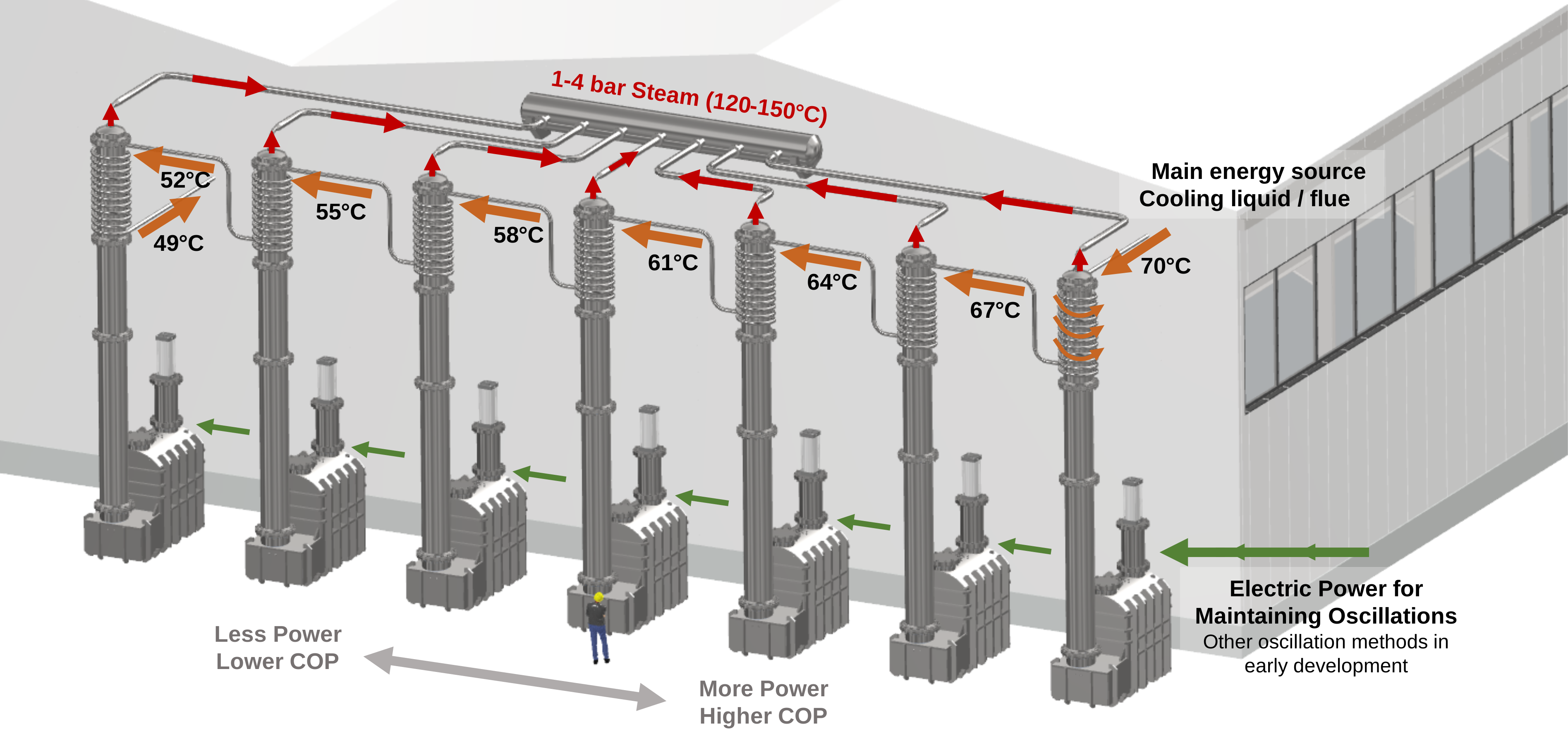
Example of several Inertial Evaporators ejecting steam into same steam header. Heat exchangers located at the top of the system extract waste heat and offset the evaporative cooling inside each system. Waste heat stream is returned when required cooling has been achieved. An accumulator or heat exchanger can also be used. Liquid condensate return and make-up water supply are not shown.
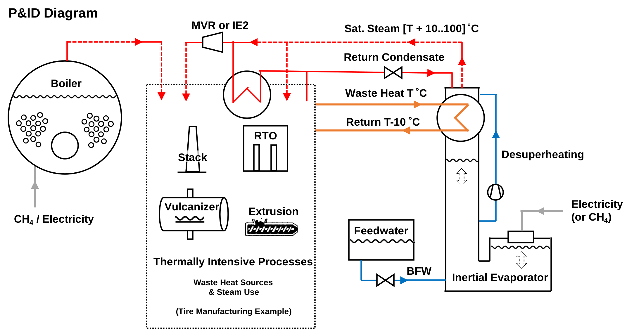
An example P&ID diagram showing boiler system connections. Note that the system is agnostic regarding input/output temps. Extremes are modeled - not yet experimentally demonstrated.
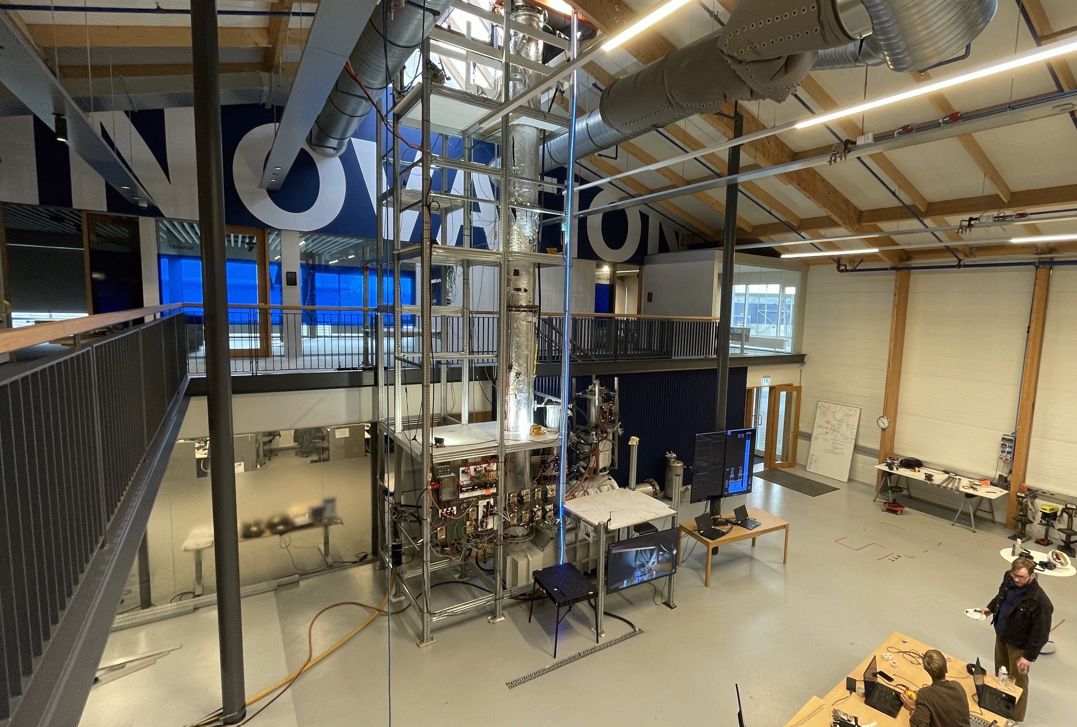
Image of Hydram’s latest Inertial Evaporator prototype at the company's dedicated 1,000 sqm. high-tech development facility. The system is three stories high, weighs 6 tons and gently assists the natural oscillation of a two ton liquid slug.
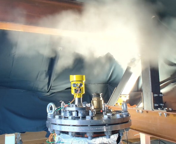
System rhythmically ejecting steam every ~2 sec. Still image from a video camera aimed at the top. Shown w/o steam header or condenser unit (for a more dramatic visual effect).
Papers & Presentations
Hydram cultivates close cooperation with academia, but the key in-house emphasis is the commercial development of Inertial Evaporator systems. A limited amount of published material is therefore in the public domain by Hydram's engineers and scientists.
Below are a presentation and an abstract from the high-temperature heat-pump symposium in Copenhagen in February 2026, which already feel a bit dated.
Industrial Waste Heat — Brief Summary
One third of the world's energy is used by industry to manufacture everything we take for granted in our modern world. For example fertilizer, paper, foodstuffs, textiles, plastics, rubbers, all oil products, steel, cement etc. etc.
To improve energy efficiency, lower costs, and reduce emissions, most industrials implement ways to recover and reuse otherwise wasted thermal energy. The most common approach leverages solutions like cleverly arranged heat exchangers that transfer heat directly from hot process streams that need cooling (such as exhaust gases and cooling water) to streams that require heating. In many cases, excess heat is furthermore collected and exported to a nearby district heating network, greenhouses, or an adjacent industrial process.
Despite these efforts, a substantial portion (20-50% depending on sector/process) of the energy is discarded as ultra-low-grade waste heat (lower than ~60°C). This low-temperature heat is difficult to reuse because most industrial processes require steam or higher-grade heat (130-170°C or above). As a result, many plants are forced to shed this thermal energy to the atmosphere via radiators or simply pour it down the drain as warm cooling water.
Current Alternative Systems
An established category of solutions for upgrading such low-grade waste heat into process steam is the integration of Large Heat Pumps (LHP) with Mechanical Vapor Recompression (MVR), typically via so called flash tanks. These combined "LHP + MVR" system packages are offered by established OEMs and technology providers, including Howden, Turboden (a Mitsubishi Heavy Industries group company), GIG Karasek, Piller Blowers & Compressors, Atlas Copco, and others.
A typical LHP + MVR system consists of three steps:
- A closed-cycle large heat pump first upgrades the available low-grade waste heat. It does so by concurrently cooling a ~40°C waste-heat source, thus extracting its thermal energy which it uses to heat up thermal fluid to a higher intermediate temperature level, 70-90°C, or more in the case of high-temperature heat pumps (HTHPs). It's similar to how refrigerators work, cooling the food inside by moving the "inside-heat" energy to the hot coils that used to be visible on the backside of refrigerators.
- The intermediate heat from the thermal fluid is transferred to an evaporator vessel (often referred to as a vacuum flash tank). The tank is operated at sub-atmospheric pressure which reduces the boiling point of the water in it. Due to the reduced pressure the 80°C thermal fluid from the heat pump is sufficiently hot to boil the water in the evaporator vessel and generate low-pressure steam or vapor from the water (or process condensate).
- One or more MVR compressors then extract and compress the low-pressure vapor. The rapid and powerful compression simultaneously increases the steam's pressure and temperature, quickly turning it into useful saturated steam suitable for direct process use, typically in the range of 130-170°C or higher, depending on the number of compression stages and system design. Because steam becomes superheated when it is "squished" the process is typically in several stages allowing for the repeated removal of its superheat (it's not really the temperature but the extra pressure of superheated steam no one really cares for).
The LHP + MVR approach enables process steam generation from waste heat supplementing steam already generated by existing plant boilers. Generating process steam this way can be far more cost-effective than producing the same amount in on-site gas boilers. An important caveat is the fact that electrical energy is typically 3-5x more expensive (per Joule) than natural gas. Because of this unfortunate price discrepancy, the efficiency (COP) of electrically driven waste-heat upgrading equipment is of paramount importance.
The design and specifics of LHP + MVR systems and high-temperature heat pumps vary between manufacturers, and size ranges from a couple of kWth to several MWth. The technology is now considered mature and has been successfully integrated in thermally intensive industries such as pulp & paper, food/beverages and chemicals.
Other technical solutions are less mature or have attributes making them less comparable to Hydram's solution (such as ORCs, AHTs, THTs, TVRs, thermoelectrics and others).
Sources & Links
- GIG KarasekWaste Heat Utilization ↗
- GIG KarasekIndustrial Waste Heat Utilization ↗
- Piller / BASF / GIG11-Stage Compressor System for BASF ↗
- TurbodenLarge Heat Pump Solutions ↗
- IEA HPT Annex 58High-Temperature Heat Pump Technologies (PDF) ↗
- ScienceDirectIndustrial Waste Heat Recovery — Journal Article ↗
FAQ
Inversely, systems like heat pumps and refrigerators belong to a class of "Closed" systems where the same refrigerant goes round and round traveling through all the copper coils evaporating then condensing again (a particular drop of refrigerant probably goes two rides in that roller coaster every minute or so).
All of the processes should be familiar to a second year B.Sc. engineering student. Because of the non-linearity of the oscillatuions and asymmetry of the pressure profile it is uphill to do in a clean mathematical manner. What has worked for us at Hydram is to model the system in key parts (e.g. high-pipe thermodynamics, side tank thermodynamcis and kinematics) then unite them and have the computers step through it in tiny time increments. A force based model is the first approximation but a more complex energy based model and stepping will give you more accurate results.
- Model the water's kinematics (location, velocity and acceleration). Either model the forces acting on the liquid: (i) gravity, (ii) gas pressure in the side tank, (iii) steam pressure at the high pipe, and factor in some head loss because of the “bending” of the liquid and its momentum changes as it goes in and out of the side tank. An even better and more accurate way is to use an energy-based model and track how energy travels from the potential energy of the liquid, to kinetic energy and the potential energy of the two gas regions.
- Model the side-tank gas bubble. A simple gas model will do here, although reality is more complex: partial pressure, humidity, heat transfer, etc. This section is the first place to start when thinking about how to excite the oscillation, for example by alternately increasing the pressure behind the liquid piston (in its direction of travel) and decreasing the pressure in front of it.
- Model the steam (pressure, temperature and mass) in the high pipe as available volume is alternatively expanded and reduced. This requires a basic understanding of thermodynamics and the use of a fluid-property library such as CoolProp. During the expansion of the available volume in the high pipe, the model needs to capture expansion of steam already in there, followed by evaporation of new steam. The compression can be modeled as “wet compression” (where the steam follows the condensation line) or a mixture of isentropic compression with heat loss and condensation. When the pressure exceeds ejection pressure, the model captures ejection instead of further heating.
Then one has the data to estimate power output, COP, etc.
Currently (Sept. '26) we're designing our third ejecting prototype which we'll be able to operate for several days at a time, decently powerful (tens of kWth) and COP over 1. Hydram is also in discussion with industrial companies regarding an on-site pilot installation. There we'll be able to strengthen our integration experience, iron out any kinks and perform long-period operational runs with the system in its “natural habitat”.